Summer 2009; 3D modeling, prototyping, ergonomics testing
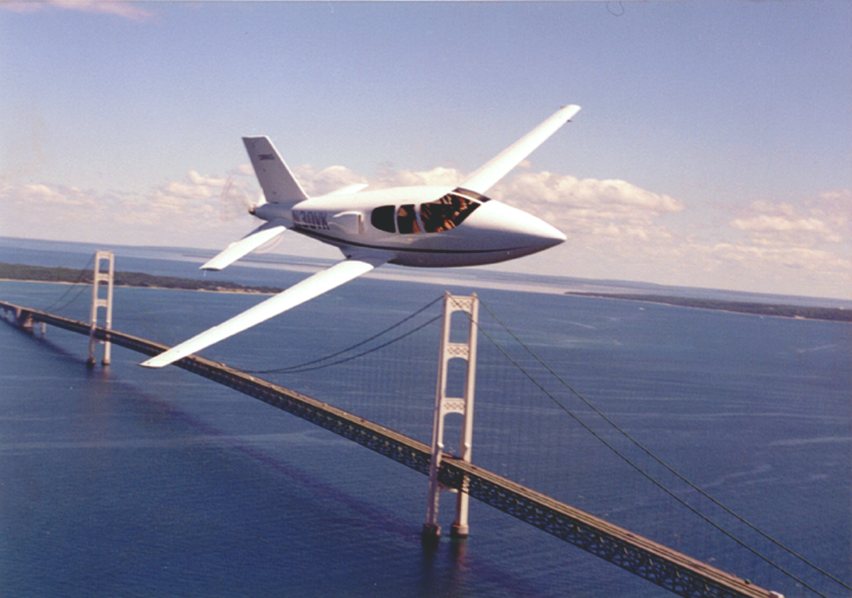
VK-30: An Experimental Aircraft
RA Mills Corporation specializes in building and modifying VK-30 kit airplanes. Since 1994, RA Mills has redesigned nearly every component for this aircraft; I was privileged to spend a summer as an intern, working with them to develop interior components.
The work
RA Mills a specialty design and fabrication company based in Medina, Ohio, knows what it takes to turn an idea into an elegant, tested, manufacturable product. As an intern during the Summer of 2009, I spent nearly four months sketching, 3D modeling, prototyping, and manufacturing brand new components for the VK-30 experimental aircraft. Owner Rick Mills, designer and fabrication expert Tim and I often worked as a close-knit team. RA Mills currently sells a pilot seat that was a primary focus of mine.
The challenge
Throughout the summer, the challenges I faced followed two themes: make it real as soon as possible, and design with the end in mind. Everything I helped design RA Mills would have to manufacture (or outsource), forcing me to consider our manufacturing capabilities, material costs, and labor to realize a design.
What you'll find here
The following series of images is an in-depth, blog-style account of my work during the Summer of 2009. You'll find loads of process, and insight into small scale design & manufacturing.
More info
For more information on RA Mills and their work, visit the website at RAMills.comInterior Trim & Overhead Console Development
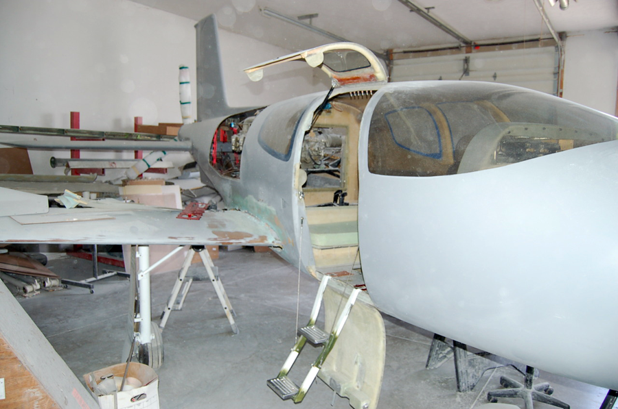
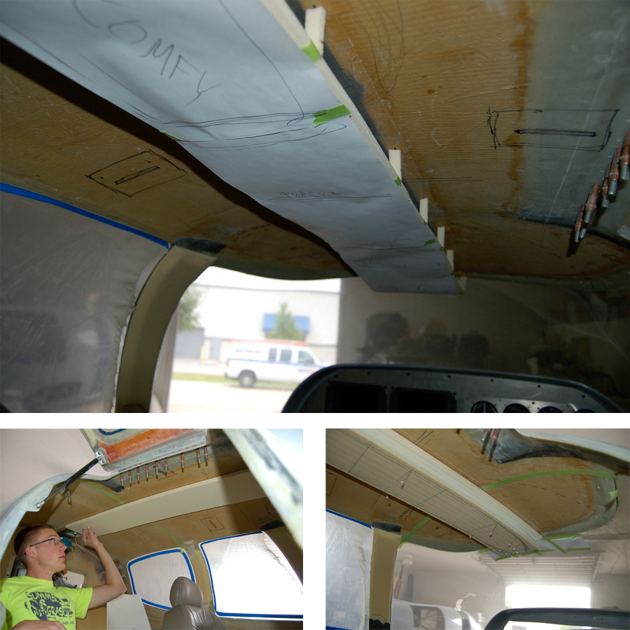
The initial goal for the summer was to develop an interior for the VK-30. This is one of four airplanes in RA Mills’ shop, and also the main airplane used for measurements and testing during the following weeks.
Several interviews with VK-30 builders and owners were conducted to attain information about wants/needs in an interior.
Several interviews with VK-30 builders and owners were conducted to attain information about wants/needs in an interior.
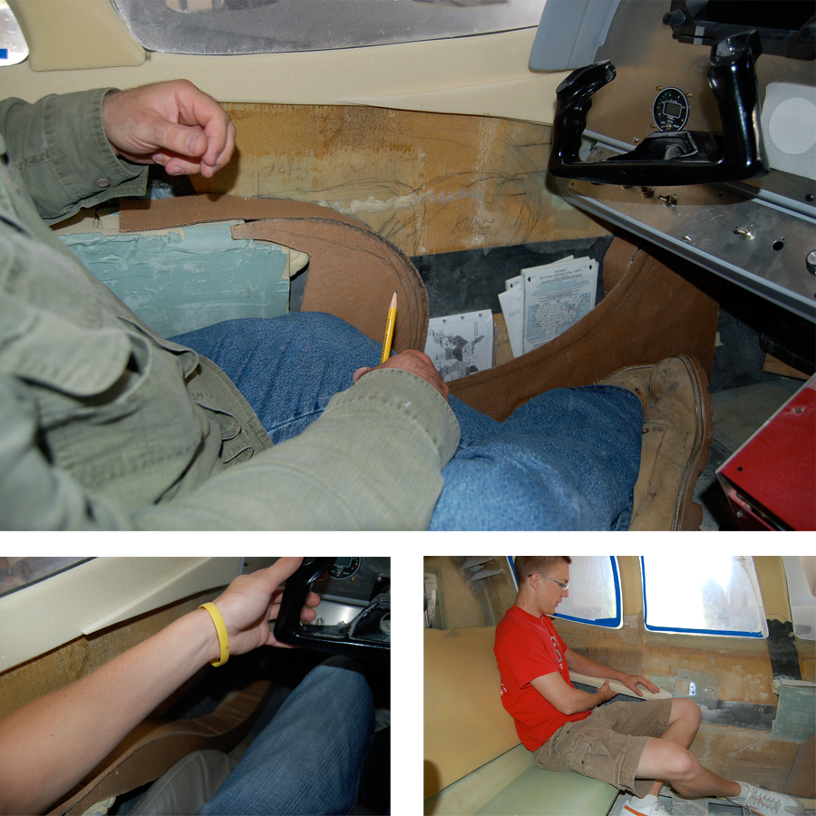
Some initial spatial studies involving the position of the pilot and co-pilot in relation to a front armrest and storage compartment. These were conducted in foam, cardboard, and anything else we could get our hands on!
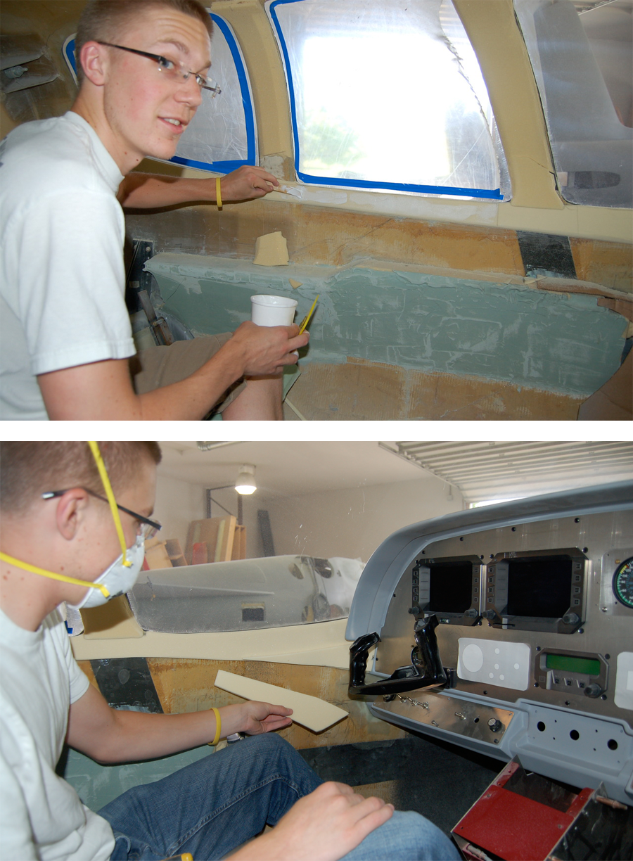
Dealing with some foam form exploration on window-trim. Rick, Tim and I spent some time deliberating on the best way to divide up the different trim sections.
The next task to tackle was the overhead console. I spent several hours discussing the console’s function with Rick, Tim, and several VK-30 owners. A paper and foam mock-up helped me to rough out the locations of certain desired features (like lights, vents). I then bonded layers of foam together to carve out the console shape.
“You have to get to a physical model as soon as possible; you can do all the sketching you want, but without a physical representation, you have nothing.”
- Rick Mills
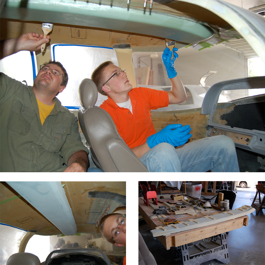
I spent a lot of time shaping and body-working the overhead console model, learning from Tim along the way. Rick, Tim and I constantly discussed its shape/volume/etc during this process. The goal was to end up with a shape from which we could pull a fiberglass mold to make production parts.
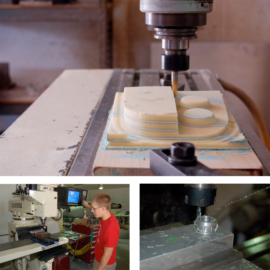
I had been learning to take a Solidworks file, import it into GIBBS to write a program for the mill, and then run the mill myself. This is a foam “plug” using this process, then fiberglassed to make a mock-up overhead console plate.
I also used shop’s lathe and mill (with Rick’s guidance) to machine an aluminum air-vent nozzle.
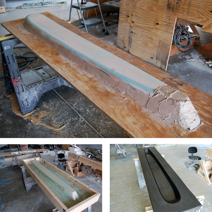
With a little more guidance from Tim, I body-worked our foam and bondo model of the overhead console into a mounted and finished “plug.” After it was complete, we made a fiberglass mold of the overhead console, which will now be used to make production parts.
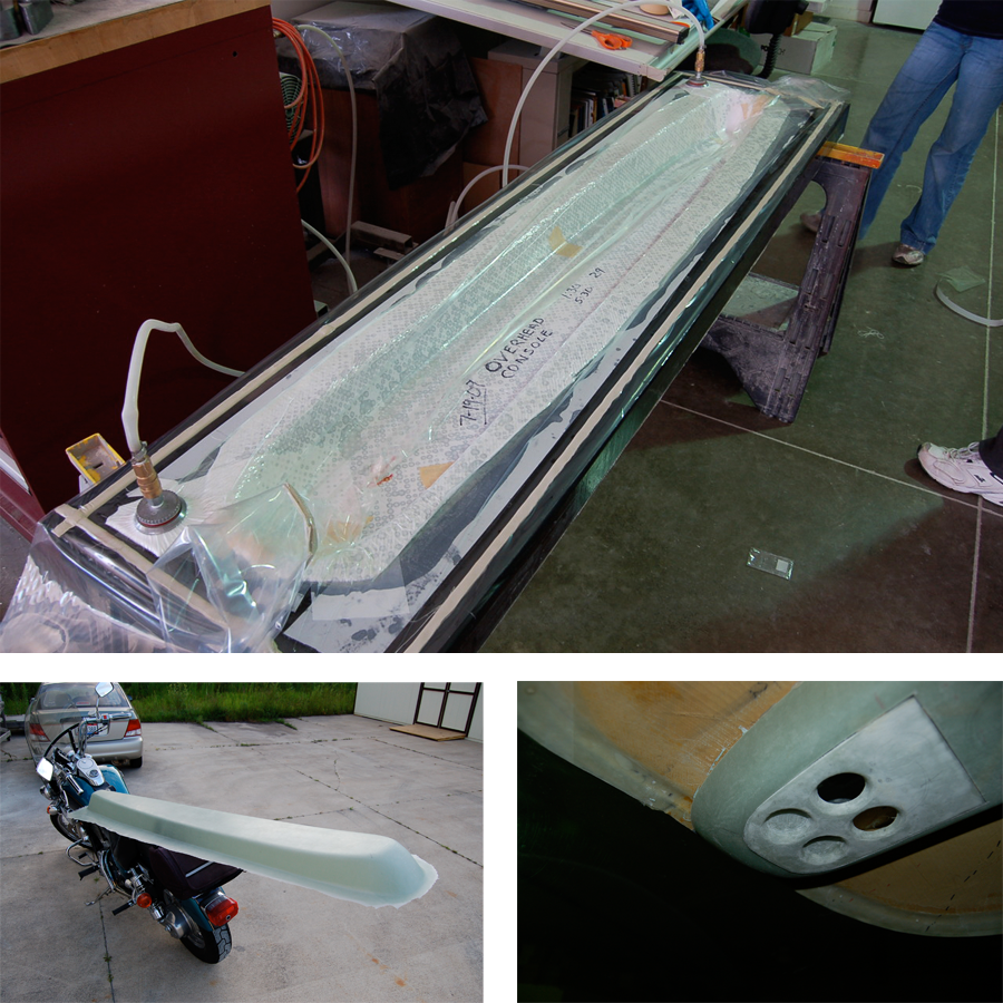
Now that we have a mold, making parts is a breeze! Rick and Tim taught me how to prepare all of the materials to vacuum-bag a fiberglass part.
Pilot Seat Development
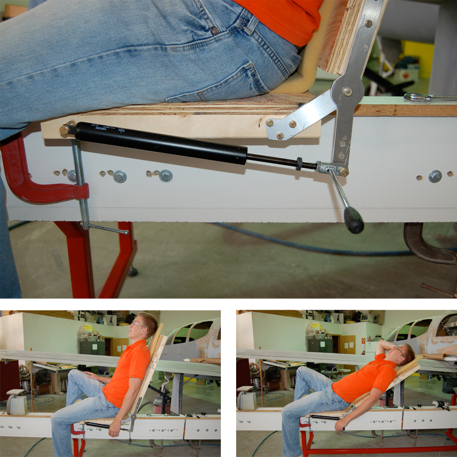
Having put a dent in the interior window trim, armrests and overhead console, Rick decided it was time to get started on the pilot and co-pilot seats. After some ergonomics research (both secondary and first-hand in the plane), and after finding a “lockable” gas-spring, I constructed a basic seat model to test the gas-spring.
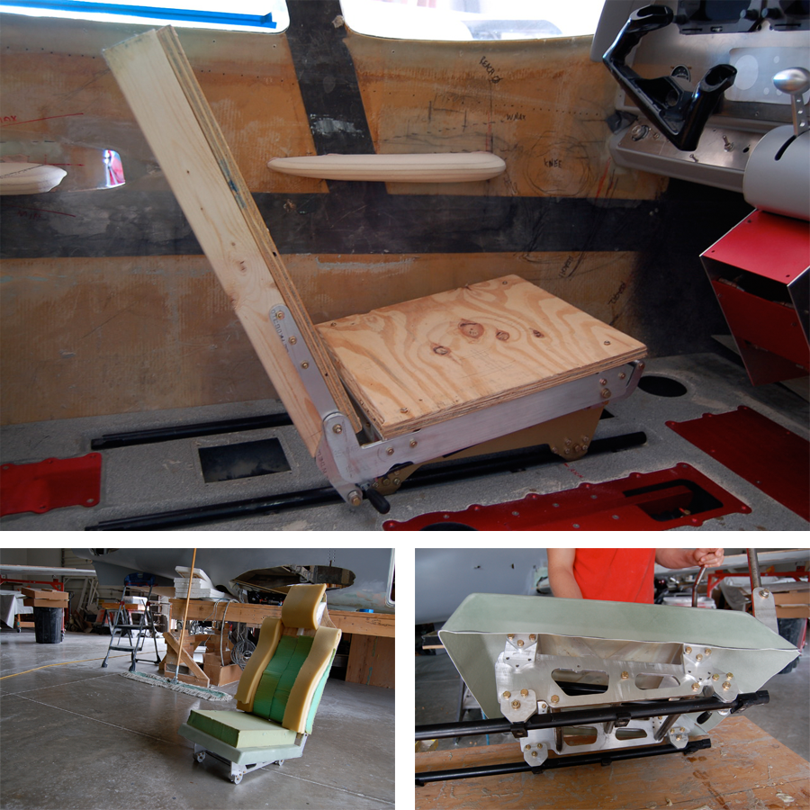
The next several weeks were spent making SIX different prototype seats, frames, and their mechanisms for tilting and articulating. Each model was thoroughly tested in the cockpit, documented, and then improved upon in its next iteration. I have a ton of data, sketches, Solidworks models, etc. from this process. I designed and machined many of the frame parts out of aluminum, though Rick and I worked as a team for the most part.
The pictures above are merely a gross oversimplification of the process and development they represent.
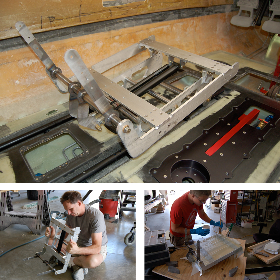
Here are a few more pictures from the development of the seat frame. Rick’s friend and associate Steve taught me a little about Solidworks finite analysis to help test and optimize the seat frame components when a simulated load is applied.
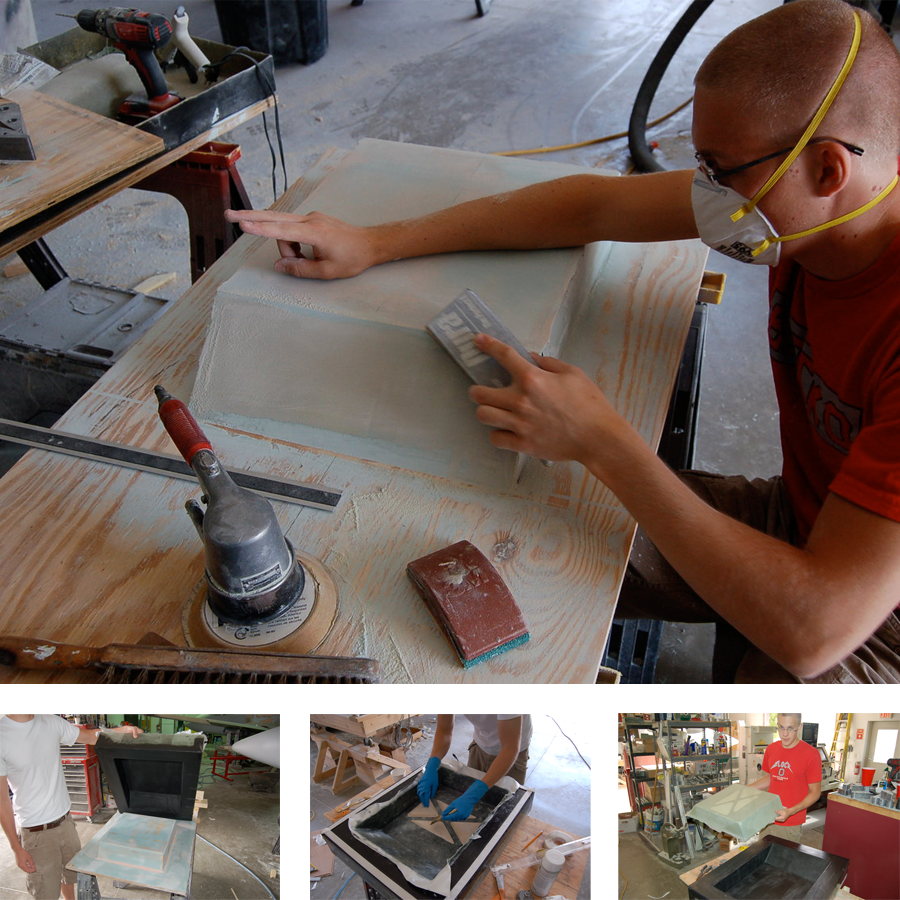
After completing the seat frame, the next logical step was to make the seat base and seat back. More fiberglass parts means more practice on plug-making, mold-making, and vacuum-bagging production parts!
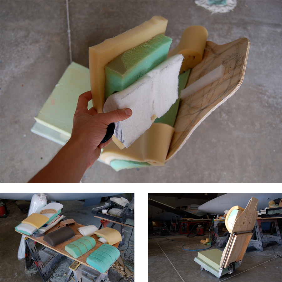
A significant part of the seat-back development was deciding whether or not to include a headrest, and how it would be incorporated if we did include one. I made several iterations of headrests out of foam for physical testing. One particular challenging aspect of the headrest was that it had to accommodate someone 5’2” and also someone 6’3” tall!
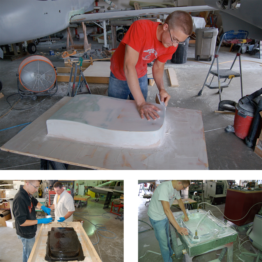
Seat-back development, like the seat base, had to remain mostly flat so the Cycle Solutions guys could work their magic with their foam (under the upholstering). After deciding on a shape for the back, based on more ergonomic research and planning (where to attach the frame, etc.), I made another plug, then mold, then part.
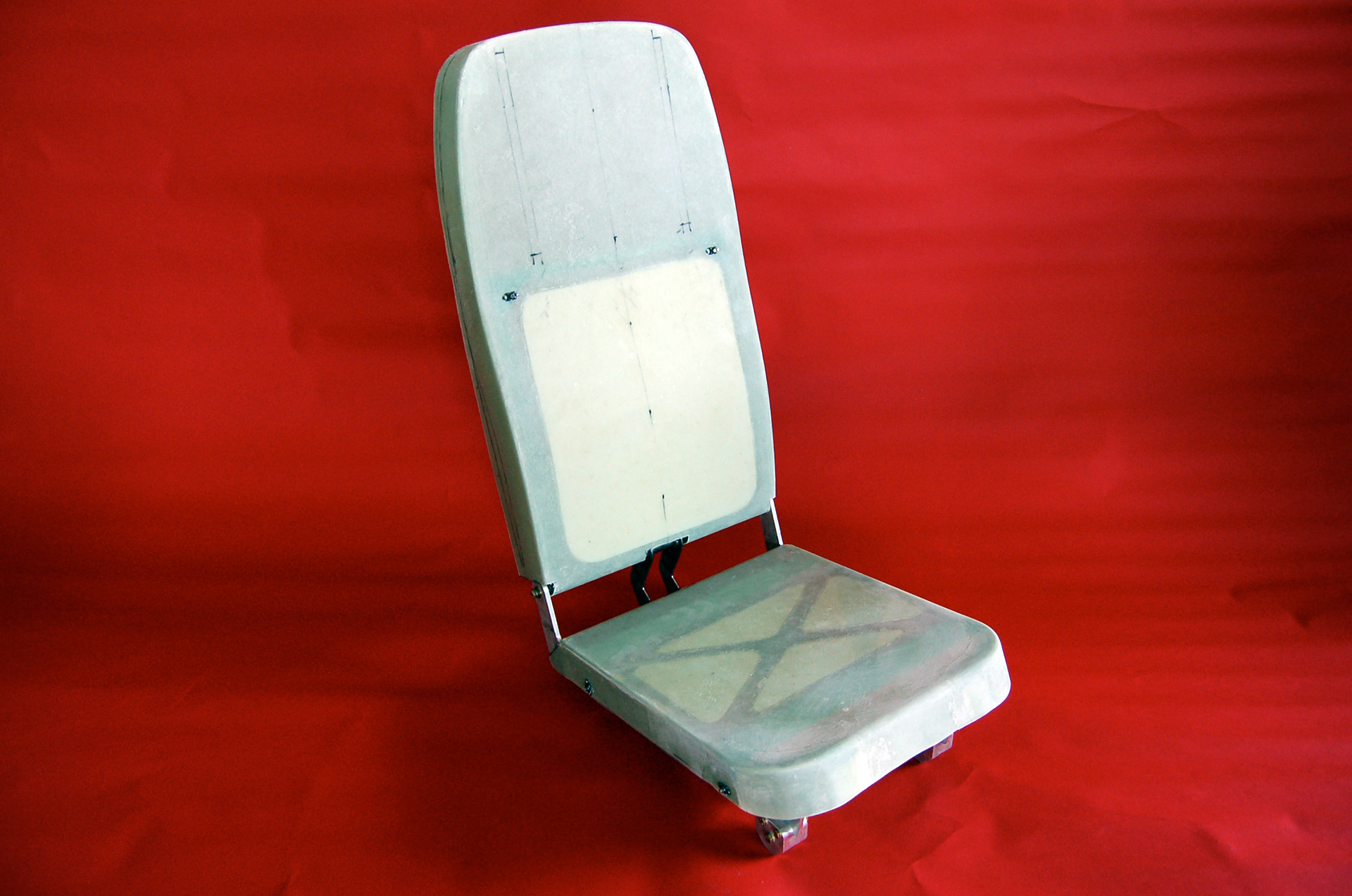
Finally, the seat frame with trimmed fiberglass seat-base and seat-back pans, attached with nut-plates, ready to go to Cycle Solutions for foam.